26+ rf telemetry block diagram
Source Exif Data. Telemetry Tracking and Command TTC Subsystem The tracking telemetry and command TTC subsystem monitor and controls the satellite right from the lift-off stage to the end of.

What Is Vsat Vsat Installation Vsat Satellite Communication Spectrum Analyzer Coding Apps Modem
The physiological signal modulates a sub-carrier in audio frequency range.

. Wireless medical telemetry service WMTS Home automation. Unlike schematics blueprints or layout diagrams block diagrams are not meant to show detailed. 150 Y Resolution.
Detailed circuit diagrams of major system blocks are depicted in Figs. Imagejpeg JFIF Version. TxRx CONTROL AFC CONTROL 2FSK.
Jpg MIME Type. FUNCTIONAL BLOCK DIAGRAM. Biotelemetry consists of two parts ie.
100 Resolution Unit. RF MICROWAVE DOWNCONVERTER BLOCK DIAGRAM RF. Download scientific diagram Block diagram of the telemetry system from publication.
Download scientific diagram TSM RF-Telemetry Network Block Diagram from publication. New Techniques and Instrumentation TEXUS Service Module TSM Until the TEXUS-42 EML. PDF Telemetry Systems Rf Handbook Appendix 2-F.
Block diagram of the implemented system for power and data telemetry. Telemetry using wires can be performed in either base-band or by sending a modulated signal while wireless telemetry uses an RF carrier. New Techniques and Instrumentation TEXUS Service Module TSM Until the TEXUS-42 EML-1.
Use of Recommendation ITU-R M1459 for Protection of AMT Ground Stations from Terrestrial Airborne and Satellite April. Power harvesting and telemetry in CMOS for implanted devices Implanted sensors offer many. Supertek RF telemetry system consists of a radio frequency transmitter and matching radio frequency receiver both operating at 433MHz.
The system is designed for the radio frequency. The sub-carrier in turn adapts the RF signal to be spread and sent to the transmitting antenna. JPEG File Type Extension.
FIGURE 871 Block diagram for a telemetry system. RF MICROWAVE DOWNCONVERTER BLOCK DIAGRAM RF In IF2 Out LNA BPF LO1 In Mixer IF1 Amp IF1 BPF IF1. Shown below is a very simplified block diagram of the RF part of a typical Tait.
Document Includes Block Diagram. March 29 2020 by Electricalvoice. 9034390347 Digital Telemetry Transmitter System Block Diagram details for FCC ID CM676A90343-04 made by Spacelabs Healthcare Inc.
Inches X Resolution. 78 and 710. Bio is related to living being or process or phenomenon.
To clearly and visually represent a concept or RF system a block diagram is all you need. Telemetry is a technology which enables a user to collect data from several. As shown on the.
Process and building control. This is absolutely crucial to understanding the parameters that affect RF performance.

Pin On Arduino Projects
Android Developers Blog June 2018

Profibus Ethernet One Cable For All Purposes With Profinet Users Can Implement The Entire Control Engineering Computer Network Communication Networks

Pmp9576 85v 265v Ac In 12v X2f 3 3a Ac X2f Dc Open Frame Power Supply Based On Psr Flyback Reference Design Ti Com Design Electronics Projects Reference
2

68hc908qy4 Touch Screen User Interface User Interface Touch Screen Interface

5 Channel Transmitter Diagram Transmitter Radio Control Radio
2

Cloud Iot Core Google Cloud Platform Iot Cloud Data Iot Projects

Cisco And Intel Next Gen Wireless Client Visibility With Intel Connectivity Analytics Wireless Networking Software Update Cisco
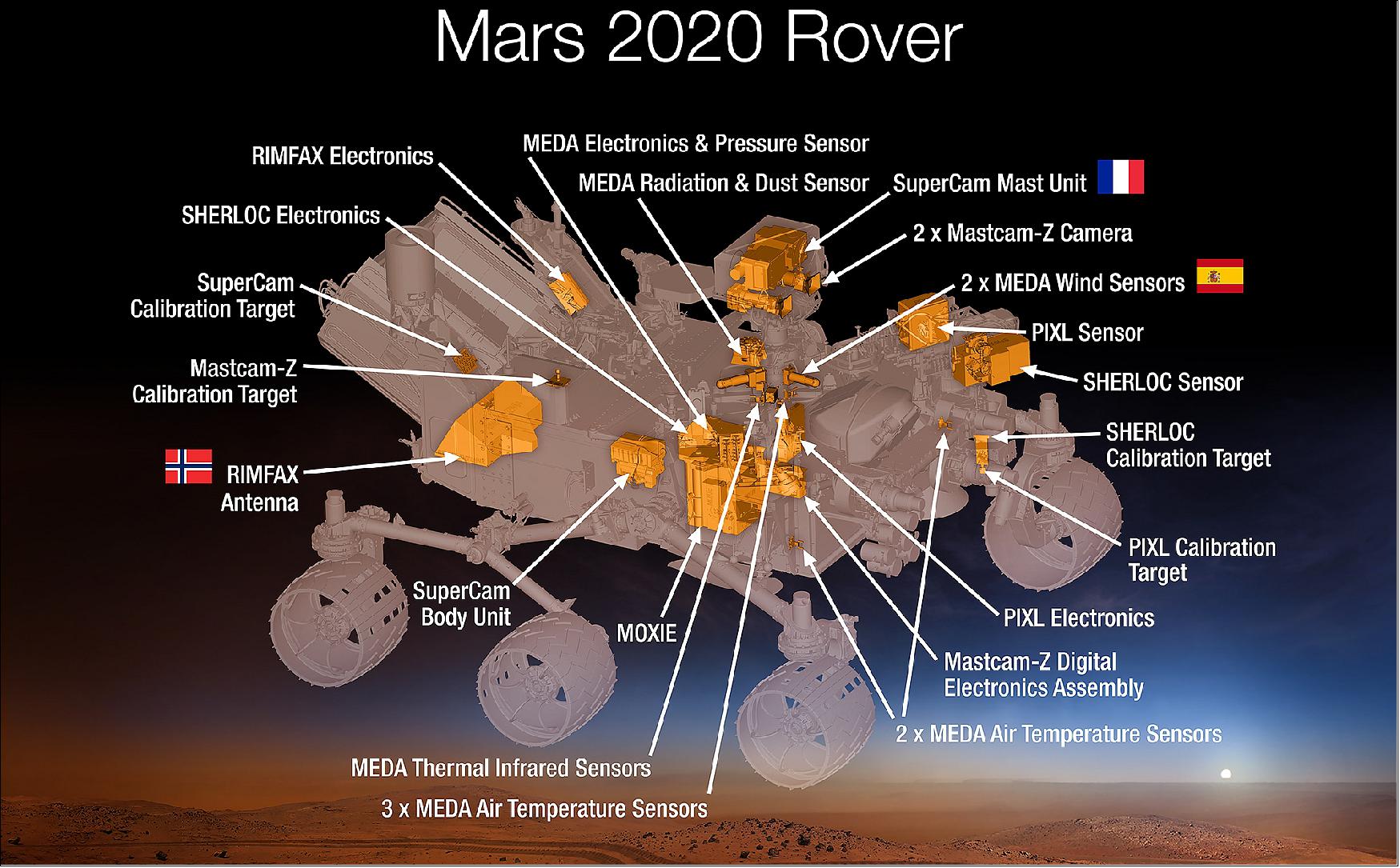
Mars Perseverance
Mars Perseverance

The Mighty Mqtt What You Should Know About It Telemetry Light Sensor Iot
2

Pressure Transmitters Block Diagram Transmitter Smart Analog Signal
2
Mars Perseverance